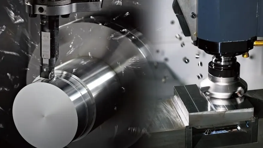



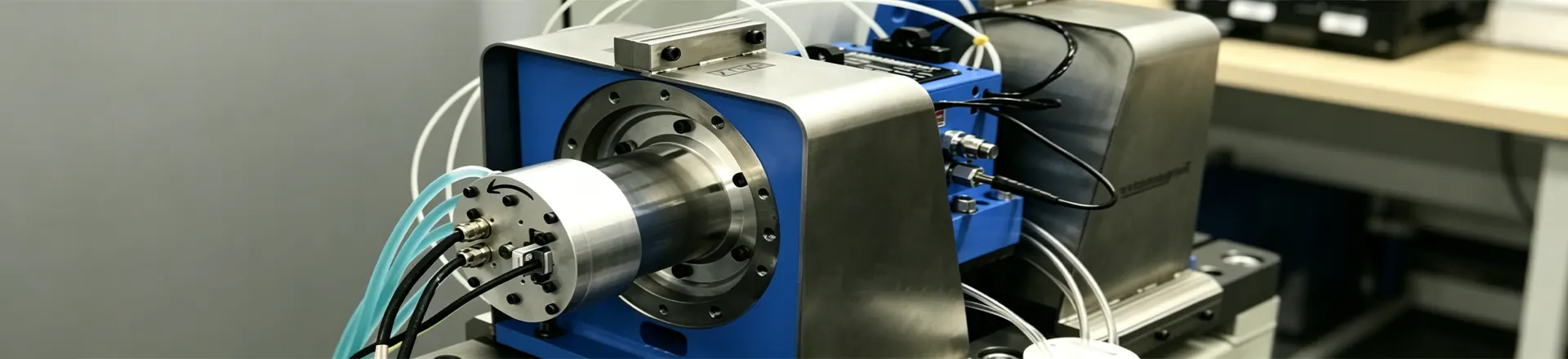
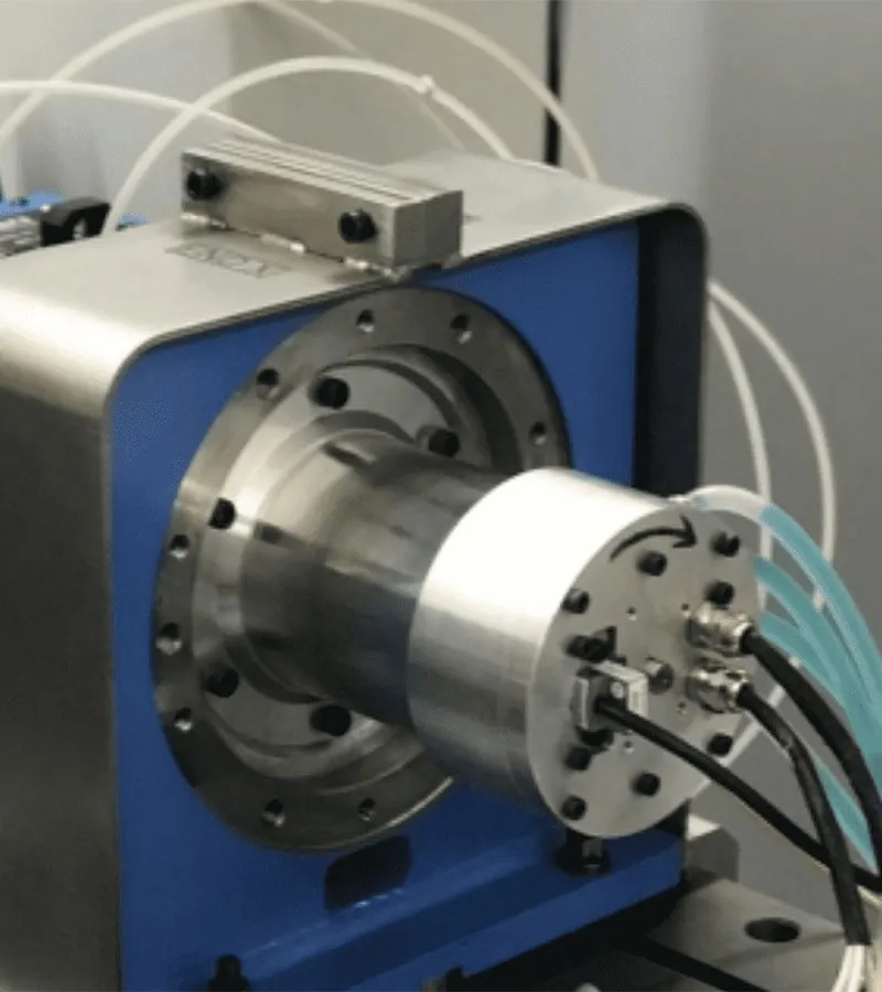
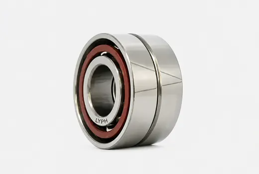
In modern high-end CNC machine tools, the motorized spindle is recognized as the "heart" of the equipment. By integrating the motor and the spindle into a single, cohesive unit, it delivers ultra-high speeds, exceptional precision, and superior surface finishes that conventional mechanical spindles simply cannot match.
Supporting this high-speed "heart" are motorized spindle bearings. Operating at extreme conditions ranging from tens of thousands to over 100,000 RPM, the performance of these super-precision bearings directly dictates the accuracy and operational lifespan of the entire machine tool.
This technical guide explores the essential design principles of motorized spindle bearings and provides proven troubleshooting solutions for common workshop failures.
1. Core Engineering Essentials of Motorized Spindle Bearings
Unlike general-purpose industrial bearings, motorized spindle bearings are classified as super-precision components—typically manufactured to P4/P2 standards. Their material science and structural designs represent the pinnacle of modern bearing manufacturing.
Why "Hybrid Ceramic Angular Contact Ball Bearings" Dominate
In high-speed motorized spindle designs, hybrid ceramic angular contact ball bearings are the industry standard. They feature premium steel inner and outer rings matched with silicon nitride (Si₃N₄) ceramic balls. Ceramic rolling elements perfectly resolve the fundamental bottlenecks of high-speed rotation:
- Lightweight Design (Minimized Centrifugal Force): Silicon nitride is only 40% as dense as bearing steel. At ultra-high speeds, this drastically reduces the centrifugal force exerted by the balls on the outer raceway, significantly cutting down frictional heat and wear.
- Superior Rigidity (High Modulus): The elastic modulus of ceramic is roughly 50% higher than that of steel. This means minimal deformation under severe cutting loads, ensuring excellent dynamic machining accuracy.
- Anti-Walling & Wear Resistance: Because ceramic and steel are dissimilar materials, their adhesive friction coefficient is exceptionally low. Even during brief periods of boundary lubrication failure, the bearing will not suffer from "scuffing" or cold welding.
- Electrical Insulation: The built-in motor of a spindle inherently generates high-frequency stray currents. Ceramic balls act as a natural electrical insulator, preventing spark discharges from etching the raceways.
Two Dominant Lubrication Methods for High-Speed Spindles
Standard grease lubrication fails at high velocity due to extreme churning heat. Consequently, advanced spindles rely on two specific delivery methods:
- Precision Oil-Air Lubrication: High-pressure compressed air acts as a carrier to deliver micro-quantities of lubricating oil (often just a few drops per hour) directly into the bearing interior. This method provides reliable thin-film lubrication while the continuous airflow actively dissipates thermal energy. It remains the premier choice for ultra-high-speed spindles.
- High-Speed Grease Lubrication: Utilizes highly specialized synthetic high-speed greases. While its speed limits (dN factors) are slightly below oil-air systems, it requires no external oiling infrastructure, lowers costs, and offers a maintenance-free, sealed-for-life setup for medium-to-high-speed applications.
2. Spindle Bearing Failures: Causes & Troubleshooting Solutions
Super-precision bearings are highly sensitive to contamination, mounting errors, and operational abuse. Below are the four most common failure modes diagnosed in machining facilities, along with detailed engineering solutions:
Failure 1: Spindle Overheating (Abnormal Thermal Spikes)
❓ Symptom: Shortly after startup, the spindle housing temperature spikes rapidly, frequently triggering the CNC machine’s thermal protection alarm.
🔍 Root Causes:
- Incorrect Lubricant Volume: For oil-air systems, a faulty dosing valve may cause over-lubrication (generating excessive fluid churning heat), or clogged lines may cause dry friction. For grease systems, it implies the bearing was packed with too much grease during a rebuild.
- Excessive Preload (Thermal Seizure Precursor): Radial and axial thermal expansion occurs at high speeds. If the spindle shaft lacks adequate axial compliance, the structural preload will multiply exponentially, locking the system into a destructive thermal loop.
- Cooling Jacket Failure: The closed-loop water chiller system is failing to circulate coolant properly through the spindle jacket, or the chiller temperature setpoint is wrong.
💡 Solutions:
Audit the oil-air lubrication unit's pressure gauges and pulse frequencies to guarantee that oil delivery is minute yet consistent.
Inspect the coolant flow rate. Set the water chiller to match the ambient shop temperature or 1-2°C below room temperature to eliminate internal thermal stresses.
If a rebuild error is suspected, recalculate and grind the spacer rings to re-establish the precise initial preload design.
Failure 2: Abnormal Vibration and High-Pitched Squealing
❓ Symptom: The spindle emits a sharp, metallic squeal during acceleration or exhibits severe resonance at specific RPM bands, leaving visible chatter marks on the workpiece.
🔍 Root Causes:
- Raceway Brinelling or Flaking: The bearing was subjected to impact forces during installation (e.g., hitting with a hammer), or a severe tool crash forced the ceramic balls to indent the steel raceways.
- Unbalance Degradation: At high speeds, minor residual unbalance in the tool holder, collet, or the spindle shaft itself generates massive centrifugal forces, inducing heavy vibrations and accelerating fatigue.
💡 Solutions:
Perform a vibration spectrum analysis on the spindle housing. If sharp peaks emerge at calculated Bearing Characteristic Frequencies (BCF), the rolling elements or raceways are damaged. The bearing set must be replaced.
Execute an in-situ dynamic balancing correction on the spindle assembly, ensuring the residual unbalance satisfies ISO G0.4 standards or better.
Failure 3: Loss of Machining Accuracy (Excessive Runout)
❓ Symptom: Workpieces experience out-of-roundness or dimensional drift. A dial indicator placed on the spindle taper or face measures static or dynamic runout far beyond tolerance.
🔍 Root Causes:
- Subsurface Fatigue Wear: The bearing is reaching the end of its fatigue life, leading to micro-spalling on the raceways and causing increased internal clearance.
- Geometrical Tolerances Degraded: Long-term thermal cycles or stress relaxation have distorted the shaft journal or housing bore, causing the bearing rings to seat at a slight angle.
Solutions:
Measure the spindle’s radial runout and axial endplay using a 0.001mm dial indicator. High-precision motorized spindles typically require a static runout of under 0.002mm (2 microns).
If runout is out of spec, disassemble the spindle and grind the shaft journal and housing bore on a precision cylindrical/internal grinder to restore geometric tolerances before installing a new bearing set.
Failure 4: Electrical Corrosion (Fluting/Electrical Pitting)
❓ Symptom: The bearing fails prematurely. Upon disassembly, the steel raceways appear blackened, and microscope inspection reveals dense, microscopic volcanic-like melt pits.
🔍 Root Causes:
High-frequency PWM pulses from the VFD (Variable Frequency Drive) induce a shaft voltage. When this voltage punctures the microscopic insulating oil film inside the bearing, an electric arc occurs, localized melting the steel surface.
💡 Solutions:
Upgrade the spindle to hybrid ceramic bearings. The insulating nature of the silicon nitride balls breaks the electrical circuit entirely.
Install a high-frequency shaft grounding brush or conductive ring at the rear of the spindle to divert shaft currents safely to the machine frame ground.
3. The Spindle Bearing Lifeline: Precision Assembly Rules
Because the tolerances of motorized spindle bearings are measured in microns, their operational lifespan is heavily determined during the assembly process:
| Assembly Stage | Mandatory Cleanliness & Technical Protocols |
| Ultra-Clean Environment | Spindle assembly must be conducted within a temperature-controlled, humidity-controlled cleanroom (Class 10,000 / ISO 7 or better). A single microscopic airborne dust particle can completely destroy a super-precision bearing. |
| Zero-Impact Fitting | Bearings and spindle shafts generally require an interference fit. Installation must utilize an induction bearing heater (heating the inner ring safely to 80°C - 100°C), allowing the bearing to slide smoothly onto the shaft. Direct impact via steel hammers or brass drifts is strictly prohibited. |
| System Break-in Protocol | Newly installed bearings must never be run at full speed immediately. A disciplined, stepped break-in routine must be enforced: start at the lowest idle speed, run for 20-30 minutes, verify temperature stabilization, and then step up the RPM incrementally until maximum design speed is reached. This process ensures optimal distribution of grease/oil films and can double the bearing's service life. |