


In modern industrial manufacturing, CNC (Computer Numerical Control) high-speed machine tools are widely recognized as the "mother machines" of manufacturing. From the precision aluminum chassis of smartphones and intricate automotive injection molds to the complex aerospace impellers screaming through the skies—the production of these ultra-precise components relies entirely on the relentless accuracy of high-speed CNC machining.
This guide delivers an essential overview of the core advantages of CNC high-speed machine tools and provides actionable diagnostic protocols for the three most common production pain points in high-speed machining (HSM) shops.
1. Technical Overview: What is a CNC High-Speed Machine Tool?
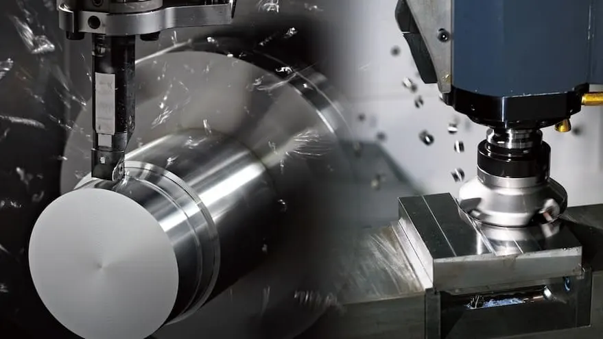
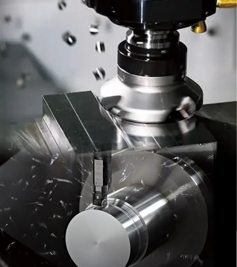
Traditional CNC machining centers typically rely on a conventional "large cutter diameter, deep depth of cut, slow feed rate" heavy-duty roughing model. In contrast, High-Speed Machining (HSM) completely flips this paradigm by utilizing small-diameter tools, shallow depths of cut, ultra-fast feed rates, and exceptionally high spindle speeds.
Why Modern Manufacturing Demands High-Speed Machine Tools
- Mirror Surface Finishes: High-speed spindles typically operate anywhere from 18,000 to 40,000+ RPM (Rotations Per Minute). At these velocities, chip formation shifts to a microscopic "peeling" action. This yields a flawless surface roughness (Ra) that mirrors polished metal, eliminating the need for costly secondary manual polishing.
- Dramatically Reduced Cycle Times: Rapid traverse rates and cutting feed rates are significantly accelerated (often ranging from 24 to 60 meters per minute), shrinking total component cycle times by 30% to 50%.
- The Cold Cutting Effect (Minimal Thermal Deflection): This is a fascinating, counter-intuitive physical property of HSM. When the cutting speed crosses a specific material threshold, over 90% of the frictional cutting heat generated does not have time to conduct into the workpiece. Instead, it is instantaneously carried away by the rapidly evacuated chips. This makes HSM the ideal choice for thin-walled automotive components and thermal-deformation-sensitive aluminum alloys.
2. Top 3 High-Speed CNC Failures & Technical Solutions
Because high-speed machine tools operate under extreme rotational velocities and aggressive dynamic forces, any microscopic alignment error or parameter drift is heavily magnified. Below are the three most prevalent workshop failures and how to solve them:
Failure 1: Periodic Patterning and Tool Chatter (Surface Roughness Failures)
❓ Symptom: The machined surface of a mold or part exhibits highly visible, wavy "chatter marks" or periodic lining. The surface finish fails inspection, and the service life of the cutting tool drops sharply.
🔍 Root Causes:
- Improper Dynamic Balance (Most Prevalent Cause): At speeds exceeding 20,000 RPM, even a 1-micron eccentricity in the tool holder or cutting tool creates massive centrifugal forces that trigger violent mechanical resonance (chatter).
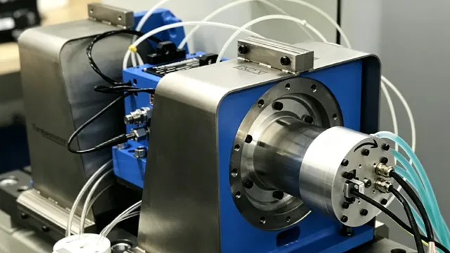
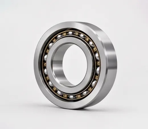
- CNC Spindle Bearing Wear: The ultra-precision hybrid ceramic bearings supporting the spindle have suffered fatigue or damage from an unrecorded tool crash, generating excessive spindle radial runout.
💡 Solutions:
Enforce Strict Dynamic Balancing Standards: The tool and tool holder assembly must be checked on a specialized balancing machine, ensuring a dynamic balance grade of G2.5 or better.
Transition to high-rigidity heat-shrink holders or hydraulic tool holders, which offer vastly superior concentricity compared to standard ER collet chucks.
Measure the spindle runout. If internal clearance thresholds are breached or acoustic anomalies (whining/grinding) are detected, arrange for an immediate rebuild using super-precision machine tool spindle bearings.
Failure 2: Spindle Overheating & Thermal Expansion (Dimensional Drift)
❓ Symptom: The machine cuts perfectly accurate parts upon morning startup, but after running continuously for two hours, the depth of cut or hole positions drift by tens of microns. The spindle outer casting feels excessively hot to the touch.
🔍 Root Causes:
The integral motor and precision bearings inside the motorized spindle generate massive frictional heat at high duty cycles.
💡 Chiller Unit Failure: The spindle oil chiller's temperature setting is improperly calibrated against the ambient machine bed temperature, or the coolant jacket channels are restricted by debris.
Solutions:
Execute a Strict Warm-Up Routine: Before running production every morning, cycle the spindle progressively through low to high RPM bands for 15–20 minutes to allow the machine structure to achieve structural thermal equilibrium.
Calibrate the spindle chiller to Ambient Temperature Tracking Mode (typically set to ambient room temperature minus 1–2°C). This stabilizes the spindle length, preventing thermal elongation or retraction.
For oil-air lubricated spindles, ensure the air supply line is thoroughly filtered through a refrigerated air dryer; moisture ingress will rupture the micro-lubricating oil film, provoking rapid bearing friction.
Failure 3: Premature Tool Micro-Chipping and Sudden Fracture (Elevated Tooling Costs)
❓ Symptom: While machining hardened tool steels or tough dies, small-diameter solid carbide endmills break suddenly without warning, or the cutting edges suffer rapid micro-chipping.
🔍 Root Causes:
- Improper Feed-per-Tooth Configuration: Machinists often run high RPMs but scale back the feed rate too aggressively out of caution. This forces the tool to "rub and scrape" rather than shear the metal, causing rapid work-hardening and thermal stress fractures.
- Inadequate Chip Evacuation: During deep pocketing or slotting, chips accumulate within the cutting zone, forcing the tool to recut old chips, instantly binding and breaking the tool.
💡 Solutions:
Calculate cutting speeds (S) and feed rates (F) precisely based on the tooling manufacturer’s formulas. High-speed machining thrives on rapid, consistent chip loading; rubbing is fatal to carbide tools.
Deploy Thru-Spindle Coolant (TSC) at high pressure or utilize high-pressure air blast rings to forcefully evacuate chips out of deep cavities.
3. The Golden Rules of High-Speed CNC Maintenance
To preserve the peak volumetric accuracy of a premium high-speed machining center, shop floor maintenance must be precise:
- The Compressed Air Line is the Lifeline: High-speed spindles rely heavily on a constant pneumatic air purge (air sealing) to prevent coolants and dust from bypassing the labyrinth seals into the bearings. Check air filters weekly; the compressed air supplied to the machine must be absolutely dry and oil-free.
- Meticulous Taper Cleanliness: The 7:24 taper or HSK contact faces of the tool holder must be wiped clean with specialized lint-free spindle wipes before insertion into the automatic tool changer (ATC). A single piece of captured micro-swarf will misalign the tool holder taper and score the internal spindle taper.
- Programmed Corner Smoothing: When writing CAM toolpaths, always use rounded blending motions (Corner Smoothing) rather than sharp 90-degree directional changes. This eliminates violent acceleration/deceleration spikes on the ball screws and preserves spindle bearing integrity.